
8 Year Exporter Swing Laser - Hand-Held Laser Cleaning Head SUP 21C – Super
8 Year Exporter Swing Laser - Hand-Held Laser Cleaning Head SUP 21C – Super Detail:
Safe. – Safe
Independent research and development of security detection system, set up a number of security alarms, security and stability
Time saving – efficient and convenient
Focus mirror, protection mirror drawer, convenient replacement
Lightness – Lightness reduces load
Smaller size, lighter weight, flexible operation, easy to use
Quality – beautiful welding- stable performance
High welding strength, small deformation, high melting depth
Performance – Multiple features
Support hand-held continuous welding, spot welding, cleaning, cutting, “hand” “since” – body, password authorization
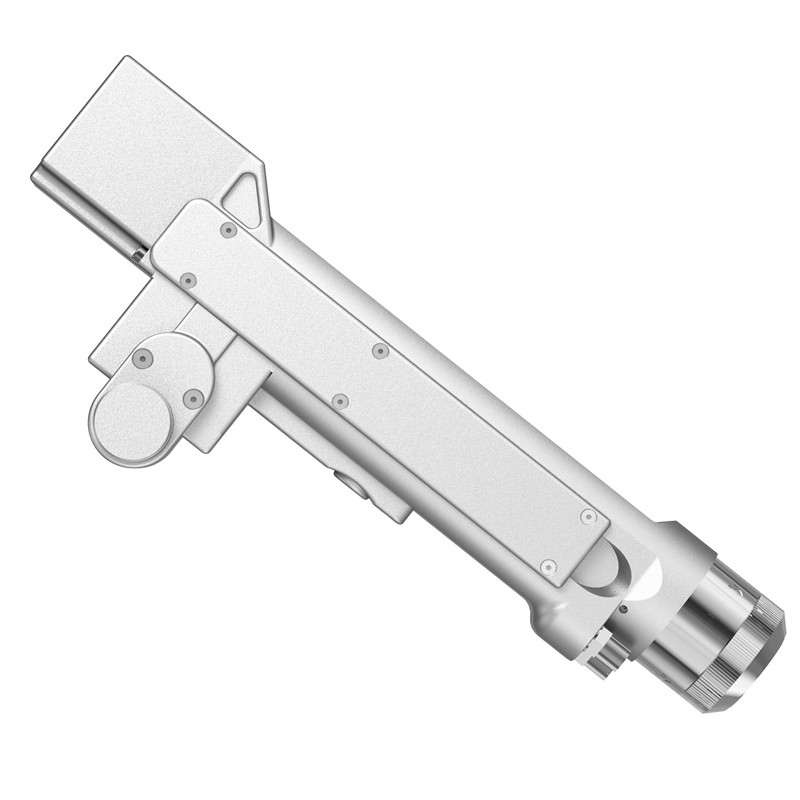
Super welding head is a handheld welding cutting head launched in 2019. The product covers hand-held welding guns and self-developed control systems, and is equipped with multiple safety alarms and active safe power and light-off settings. This product can be adapted to various brands of fiber lasers; the optimized optical and water-cooled design allows the laser head to work stably for a long time under 2000W.
1) Ensure reliable grounding before power supply.
2) The laser output head is connected with the welding head. Please check the laser output head carefully when using it to prevent dust or other pollution. When cleaning the laser output head, please use special lens paper.
3) If the equipment is not used in accordance with the methods specified in this manual, it may be in abnormal working condition and cause damage.
4) When replacing the protective lens, please make sure to protect it.
5) Please note: When using for the first time, Do not emit light when red light is not visible.
Controller wiring definition
| Plug | Definition | Signal Type | Detailed explanation | |
| Power | 1 | -15V | Enter | V2 connected to 15V switching power supply provides 15V |
| 2 | GND | Reference place | Connect to any COM of 15V switching power supply | |
| 3 | +15V | Enter | V1 connected to 15V switching power supply provides 15V+ | |
| 4 | GND | Reference place | Connect to V-of 24V switching power supply | |
| 5 | +24V | Enter | Connect to V+of 24V switching power supply | |
| Signal ground | 1 | G | Reference place | Power ground |
| 2 | R | Sender | Data exchange | |
| 3 | T | Receiving end | Data exchange | |
| 4 | V | Output | Output 24V,and ①provide 24V to the serial port display | |
| Signal interface1 | 1 | GND | Reference place | Signal ground |
| 2 | Air pressure alarm signal | Enter | Polarity can be set in the setting interface,set to low level when not in use | |
| 3 | GND | Reference place | Signal ground/The white wire of the six-core wire that is connected to the connector | |
| 4 | Water tank alarm signal | Enter | Polarity can be set in the setting interface, set to low level when not in use | |
| 5 | Securely lock the reference ground | The yellow wire of the six-core wire that is connected to the connector | ||
| 6 | Safely lock | The blue wire of the six-core wire that is connected to the connector | ||
| 7 | Welding head light switch | The black wire of the six-core wire that is connected to the connector | ||
| 8 | Welding head light switch | The brown wire of the six-core wire that is connected to the connector | ||
| Signal interface 2 | 1 | Reserved | Reserved | Reserved |
| 2 | Temperature measurement | The red wire of the six-core wire that is connected to the connector | ||
| 3 | -Shielding gas valve- | Reference place | Signal ground, 2/4 is the reference ground- | |
| 4 | +Shielding gas valve+ | Output | Output 24V, current>2A, built-in relay,directly to the air valve | |
| 5 | -Wire feed- | Wire feeder wire feed switch | ||
| 6 | +Wire feed+ | Wire feeder wire feed switch | ||
| Signal interface3 | 1 | Laser abnormal signal | Enter | Laser alarm signal |
| 2 | Laser enable+ | Output | +Laser enable+ | |
| 3 | 24V | Output | 24V power supply pin, output when power on | |
| 4 | GND | Reference place | Reference ground (enable, DA, shared ground of 3 feet) | |
| 5 | Analog+ | Output | Connect to the analog quantity of the laser, DA+ | |
| 6 | -(PWM-) RF-(PWM-) | Output | Laser pulse width modulation signal- | |
| 7 | +(PWM+) RF+(PWM+) | Output | Laser pulse width modulation signal+ | |
Controller power supply terminal
The power supply uses the 5P interface, and the supplied 24V switching power supply and 15V switching power supply are used for power supply.
Please note that the 15V switching power supply distinguishes the positive and negative poles, V1 is connected to 15V+, V2 is connected to 15V-, and any COM on the 15V switching power supply is connected to pin 2 GND!
Please note that the switching power supply must be grounded!
Controller LCD24/5000
The LCD cable is delivered with the device and can be connected directly. See the figure above for specific definitions
Controller signal interface 1
8P interface is used at the end of signal interface 1 to prepare signal
①/②pin is the air pressure alarm signal input. If it needs to be enabled (wiring is required), please set the air pressure alarm level to high in the background, otherwise it is low.
③/④ pin is the water tank alarm signal input. If it needs to be enabled (wiring is required), please set the water tank alarm level to high in the background, otherwise it is low.
Please note that any one of ① / ③ is connected to the white line of Six core wire of welding joint.
⑤ is connected to the yellow line of Six core wire of welding joint.
⑥ is connected to the blue line of Six core wire of welding joint.
⑦ is connected to the black line of Six core wire of welding joint.
⑧ is the light output switch of the welding joint,which is connected to the brown line of Six core wire of welding joint.
Controller signal interface 2
6P interface is used at the end of signal interface 2 for air valve and wire feeding
①Reserved.
②temperature measurement,which is connected to the red line of six-core wire of welding joint.
③/④pin is 24V output of air valve, and the control board has built-in relay, which can be directly connected to the air valve.
⑤/⑥Reserved.
Controller signal interface 3
①Pin is the laser alarm signal input +, if you need to enable it, please set the air pressure alarm level to high in the background
②Pin is enable+, connect to laser enable+
③The pin is 24V output, directly output 24V+ after power on
④Pet No. is a common ground (reference ground for feet 1/2/3/5)
⑤The number pin is analog quantity + output, the analog quantity is given
⑥Pin is PWM-modulated signal
⑦The number pin is PWM+ modulation signal
Controller wiring diagram
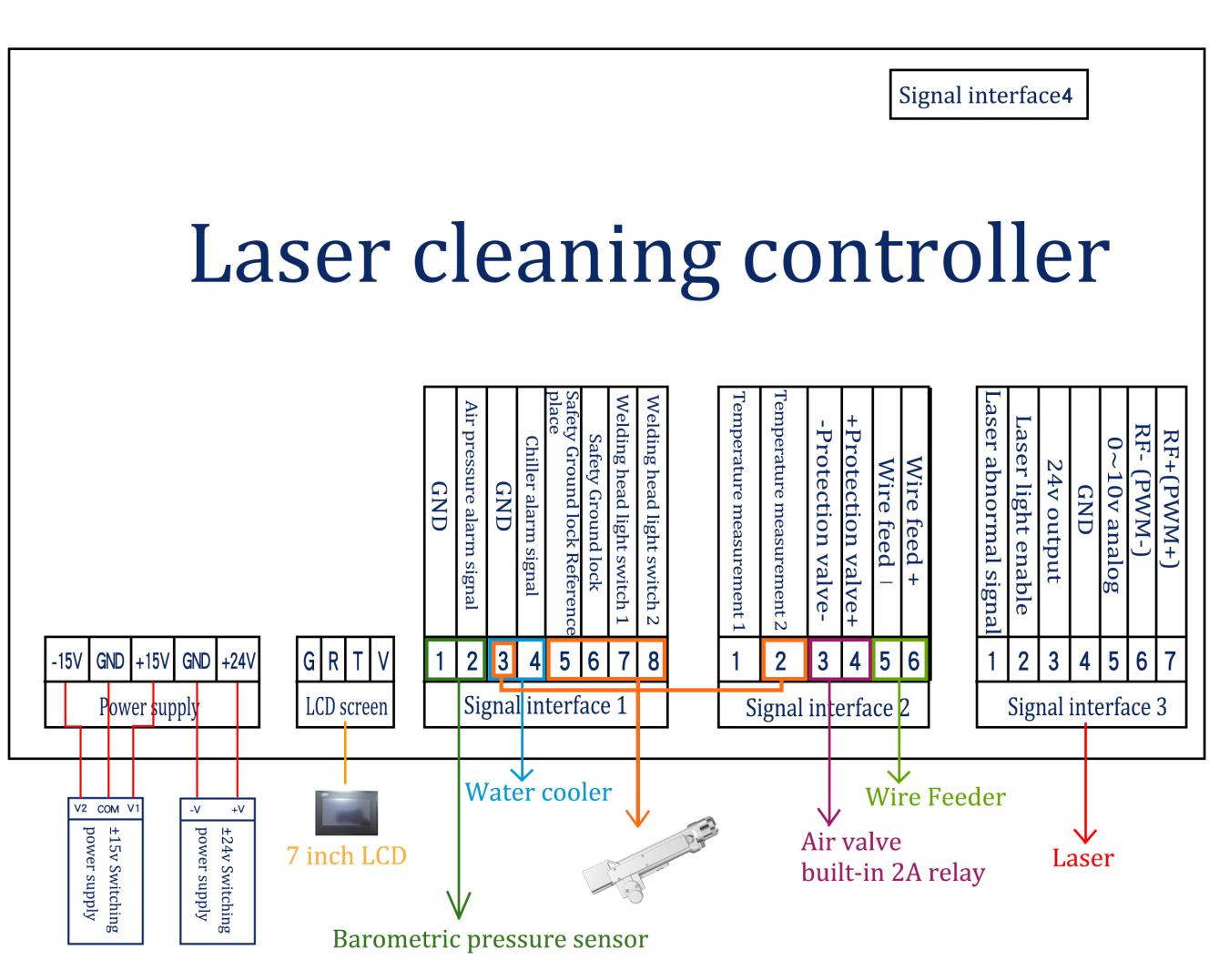
Note: The ground wire of the switching power supply must be effectively grounded!
Optical input interface
SUP welding head is suitable for most industrial laser generators. Commonly used optical fiber connectors include IPG, Ruike, Chuangxin, Fibo, Tottenham, Jept, Kaplin, etc. The optics must be kept clean and all dust must be removed before use
When the fiber is inserted, the cutting head must be rotated 90 degrees to be horizontal, and then the fiber is used to prevent dust from falling into the interface.
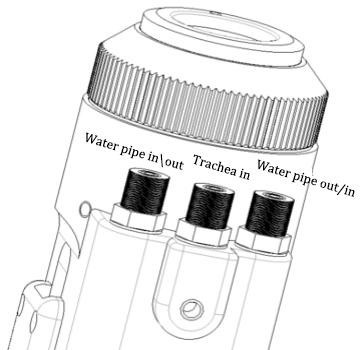
Shielding gas and water chiller interface
The water pipe and air pipe interface can be installed with hoses with an outer diameter of 6MM and an inner diameter of 4MM. The air path enters in the middle, and the two sides are Water inlet and outlet pipelines (regardless of the direction of inlet and outlet),As shown below:
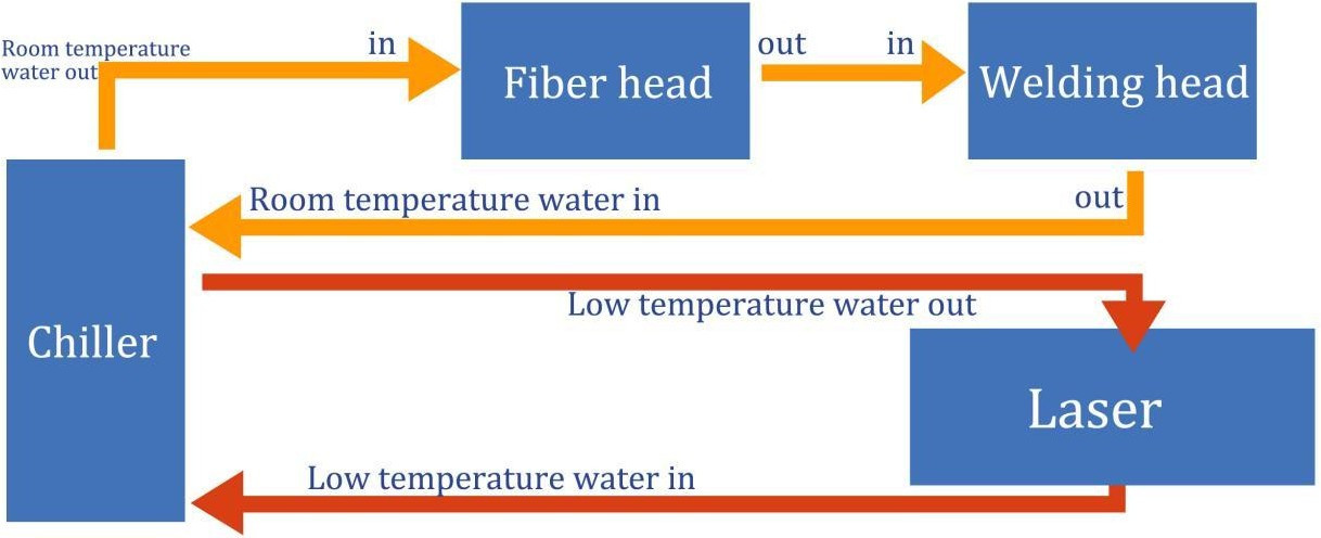
The cooling system is divided into the water circuit part of the welding head and the water circuit part of the optical fiber head, which are connected in series, as shown in the figure below:
Cleaning gun and control box connection interface
Three wires are used to connect the cleaning gun and the control box, including two motor power wires, five motor signal wires and six signal pins
2.51. The motor power / signal wires (two black) are directly connected to the motor part of the welding joint and can be removed (two options: 1. Open the motor cover and side plate of the hand-held welding gun; 2. Open the control box, both of which are plugs)
2.52. The six core signal corner uses a detachable aerial plug
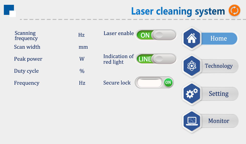
P1-1 Home,Light out
①In this interface, you can see the current process parameters (the process cannot be modified on this page) and real-time alarm information.
②In the power on state, the enable is ON by default, and the red light is LINE by default.
When the enable is turned off, “off” is displayed, and the enable signal will not be sent to the laser, which can be used to test the air outlet function
Turn off the red light indication, display “dot”, and the motor stops swinging. At this time, the red light is a point for adjusting the center
③”Safety lock”,When the “safety lock” of the gun body is opened, it is displayed as green “on” and can emit light normally. When it is closed, it is red “off” and cannot emit light.
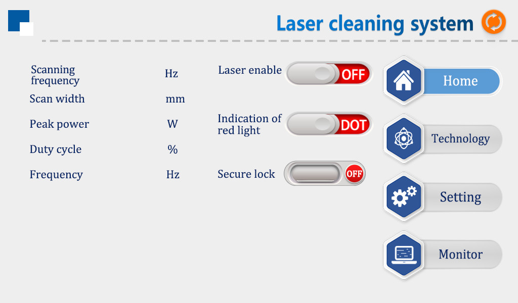
P1-2 Home,Light off
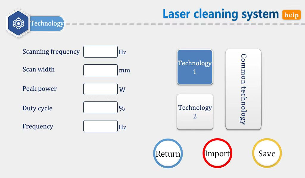
P2 process interface
①The process interface contains the commissioning process parameters. Click the box (red) to modify them. After modification, click OK, and then save them in the shortcut process. When in use, click Import (modify save import).
②The scanning frequency range is 10-100Hz and the scanning width range is 0 ^ 300mm.(the most commonly used scanning speed is 50Hz and the width is 300mm. Please note that this width should match your focus.).
③ The peak power shall be less than or equal to the laser power on the parameter page (if the laser power is 1000W, this value shall not be higher than 1000).
④Duty cycle range: 0 ~ 100 (default: 100, usually no need to change).
⑤The pulse frequency range is recommended to be 5-5000Hz (the default is 2000, which usually does not need to be changed).
⑥Click the help button at the top right to get more explanations of relevant parameters.
⑦After modifying the parameters, you can check whether the import is successful on the home page.
⑧Refer to the process in the applet.
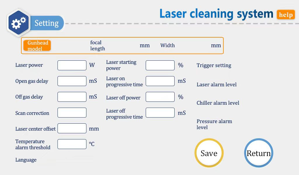
P3-1 Setting interface
Enter the password 123456 to enter this interface
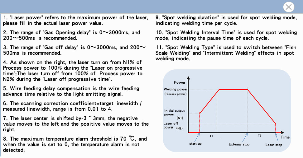
①The laser power is the power of the laser used, please fill in it correctly.
②The delay of switching gas is 200ms by default, and the range is 200ms-3000ms.
③When the light is turned on, it gradually increases from N1% of the process power to 100%; When the light is turned off, it gradually decreases from 100% of the process power to N2; (as shown in the figure below).
P3-2 Setting interface,parameter specification
④Generally, the switching optical power is 20% and the switching optical progressive time is 200ms.
⑤The maximum temperature alarm threshold is 65 ℃. When this value is set to 0, the temperature alarm will not be detected.
⑥Scan correction coefficient range is 0.01 ~ 4, coefficient target line width / measured line width: the default is 1.0.
⑦The laser center is offset by – 75 ~ 75mm, which decreases to the left and increases to the right. It should be used to adjust the red light center.
⑧The alarm level signal of air pressure / water cooler / laser is low by default. When using this alarm signal, if an external air pressure alarm is installed, it will be changed to high level, otherwise an abnormal alarm will appear, and other alarm signals are the same.
⑨Click the “Chinese” button to switch to other languages in the language selection column. At present, the standard version supports eight languages: Simplified Chinese, traditional Chinese, English, Japanese, Korean, Russian, German and French. If you need other language versions, please contact us.
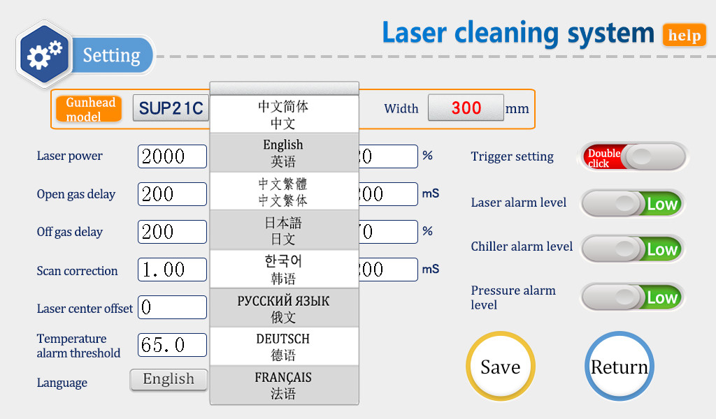
P3-3 Setting interface-language switch
⑩This page is the help page of the setting page. Long press “restore factory settings” for 3 seconds to restore all the setting parameters to “factory parameters”. Long press “save as factory settings” for 3 seconds to set the current setting parameters to “factory parameters”.

P3-4 Setting interface-help
Click the “gun head model” area to select the scanning width corresponding to different
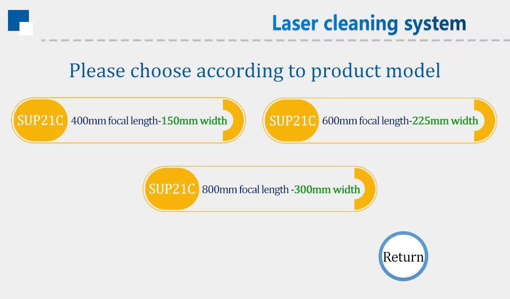
P3-5 Setting interface-switch between different focal lengths

P4 Monitor interface
This page displays the status and equipment information of each signal
Laser trigger signal: this status changes from gray to green after pulling the trigger.
Laser / water cooler / air pressure alarm signal: monitor its set high and low levels.
The output signal is displayed in the middle of the page. When the signal is output, it is gray and green.
Equipment authorization: you can authorize the use time of the equipment. When the equipment is used for more than its set time, the authorization will be terminated.
Light out time: click “device authorization”, enter ” FFFFFFBB001″ on the password page to start the timing, enter ” FFFFFFBB000″ to clear the data and stop the timing.
System version: three groups of numbers. The first group is the hardware version, the second group is the program version of MCU, and the third group is the touch screen version.
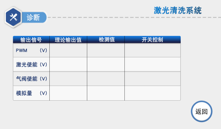
P4 Diagnosis interface
Click the “diagnosis” button to enter the diagnosis page.On this page,the laser will not emit light. You can independently output “PWM”, “laser enable”, “air valve enable” and “analog quantity” through “switch control”. Compare the detected value with the theoretical value to judge whether the function of the control box is normal.
Maintenance and replacement methods of protective lenses:
①Before operation, wash your hands with detergent and dry them, and wipe your hands again with cotton pasted with alcohol.
②Remove the screws of the protective lens cover at a relatively dust-free place, pull out the protective lens support, protect it (covered with masking paper), and check the protective lens (if there is obvious burning point on the surface of the protective lens, it should be replaced directly.)
③Then check the white power storage sealing ring under the protective lens. (if the accumulator seal ring is scratched or deformed, it cannot be used and must be replaced immediately.
④Wipe the warehouse opening and the inside of the warehouse cover with a cotton ball dipped in alcohol, quickly insert the protective mirror support into the protective mirror warehouse, and lock the screws.
Prompt laser / water cooler / air pressure alarm
①If the above alarm occurs without using the alarm signal, please change the alarm level.
②If the above alarm occurs when the alarm signal is used, check whether the alarm of the corresponding equipment or the high and low levels of the alarm signal are set incorrectly.
The screen is not lit / there is no response when clicking
①the screen is not work. if the controller is powered on (the fan is running), check whether the four core wire between the controller and the screen is correctly wired and whether the 24V voltage of the first pin and the fourth pin is normal
②If the click fails during normal use, check whether the whole machine is caused by too high temperature.
③Click action cannot be entered,Check whether the four core wires between the controller and the screen are wired correctly, and whether the second pin and the third pin are normal,See 2.1.2 LCD of controller for details
④There is no response when clicking on the newly installed equipment. It may be that the system version does not match. Just brush the program again. For SD card, please ask our company
Sudden stop of light during processing
Check whether the trigger button and other alarms are normal on the monitoring interface
Three phase power supply wiring reference of laser welding machine
Note: the two-phase or three-phase power supply depends on the power supply required by the laser and chiller, not the harness quantity

Product detail pictures:
Related Product Guide:
So as to provide you with ease and enlarge our business, we even have inspectors in QC Crew and guarantee you our best company and solution for 8 Year Exporter Swing Laser - Hand-Held Laser Cleaning Head SUP 21C – Super , The product will supply to all over the world, such as: Iraq, Lyon, Islamabad, We have more than 10 years experience of production and export business. We always develop and design kinds of novel products to meet the market demand and help the guests continuously by updating our products. We are specialized manufacturer and exporter in China. Wherever you are, please join us, and together we will shape a bright future in your business field!
We have been looking for a professional and responsible supplier, and now we find it.