
handheld laer welding gun
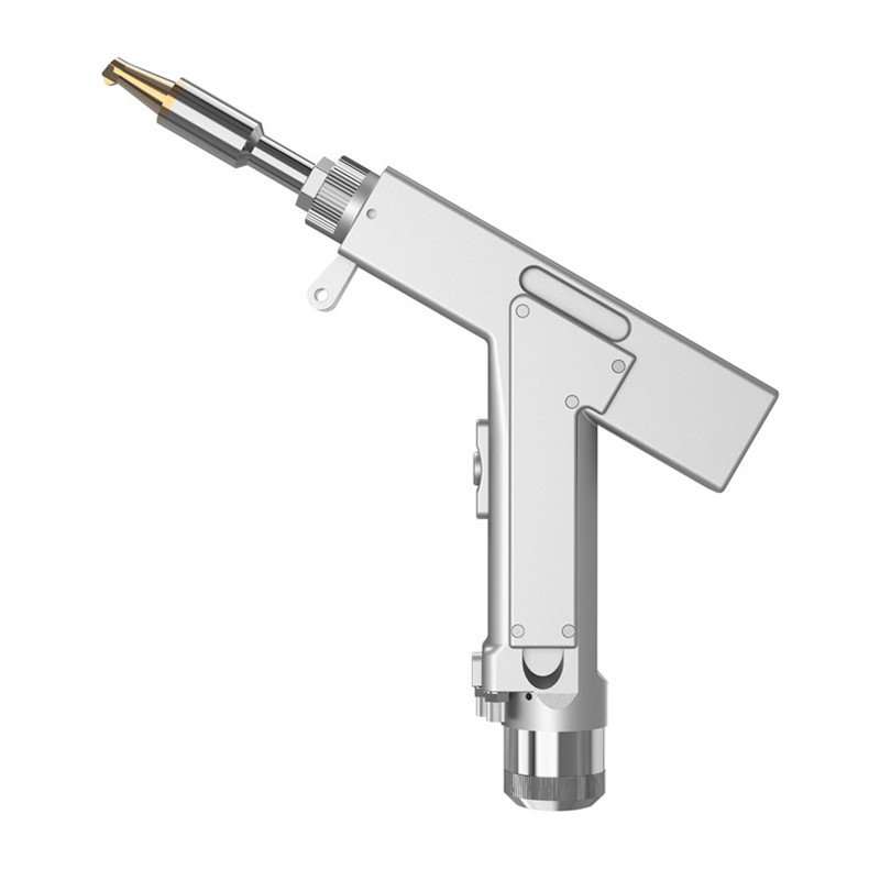
handheld laer welding gun,
handheld laser welding head,handheld laser welding head factory, laser welding head manufacturer,wholesale laser welding head,
Safety – Safety
Self-developed safety detection system with several safety alarms set, safe and stable
Time saving – efficient and convenient
Focusing mirror and protective mirror drawer, easy to replace
Lightweight —— lighter and less burden
Smaller size, lighter weight, flexible operation, easy to use
Quality – beautiful welding stable performance
High welding strength, small deformation, high melting depth
Performance – multiple functions
Support handheld continuous welding, spot welding, cleaning, cutting, “hand” “from” – body, password authorization
We are committed to strict quality control and considerate customer service, and our experienced staff will discuss your requirements with you at any time. The company’s actual annual production capacity exceeds 20,000 units, and the maximum annual production capacity can reach more than 30,000 units. Our products sell well in all cities and provinces throughout China, and are also exported to customers in the European Union and other countries and regions.
At the same time, we also welcome OEM and ODM orders. Hope we can become close and long-term partners!
1) Ensure reliable grounding before power supply.
2)The laser output head is connected to the solder head. Please check the laser output head carefully to prevent dust or other contamination when using. When cleaning the laser output head, please use special lens paper.
3)If the equipment is not used in accordance with the method specified in this manual, it may be damaged by leaving the equipment in an abnormal working condition.
4)When replacing the protective lens, please take care of the protection.
5)Please note: When using the device for the first time, when the red light cannot be emitted from the copper port, please be careful not to glow.
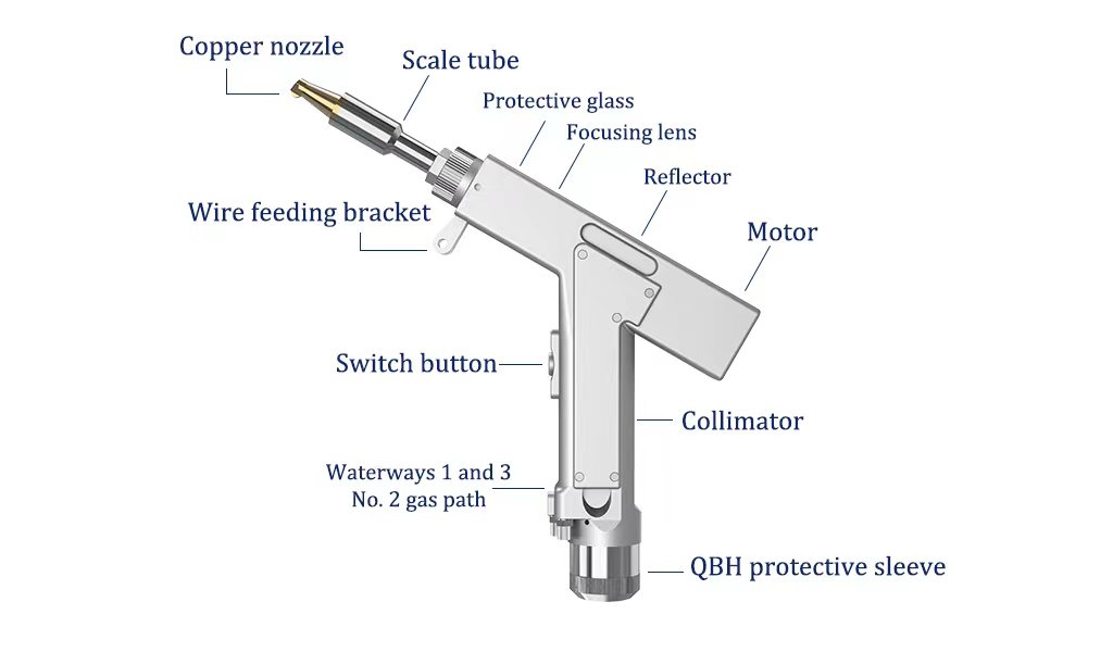
Hand-held welding head package delivery details
★First layer
SUP20S welding head 1pc
System 1 set
System cable standard 10m
★Second layer
Copper nozzle 7pcs Cutting nozzle 1pc
Scale tube 1pc
Protection mirror 10pcs
Grounding clip 1pc
Screen connection cable 1m
Display hitch 1 set
★Third layer
Display screen 1pcs
Power switch 2pcs
Controller wiring definition
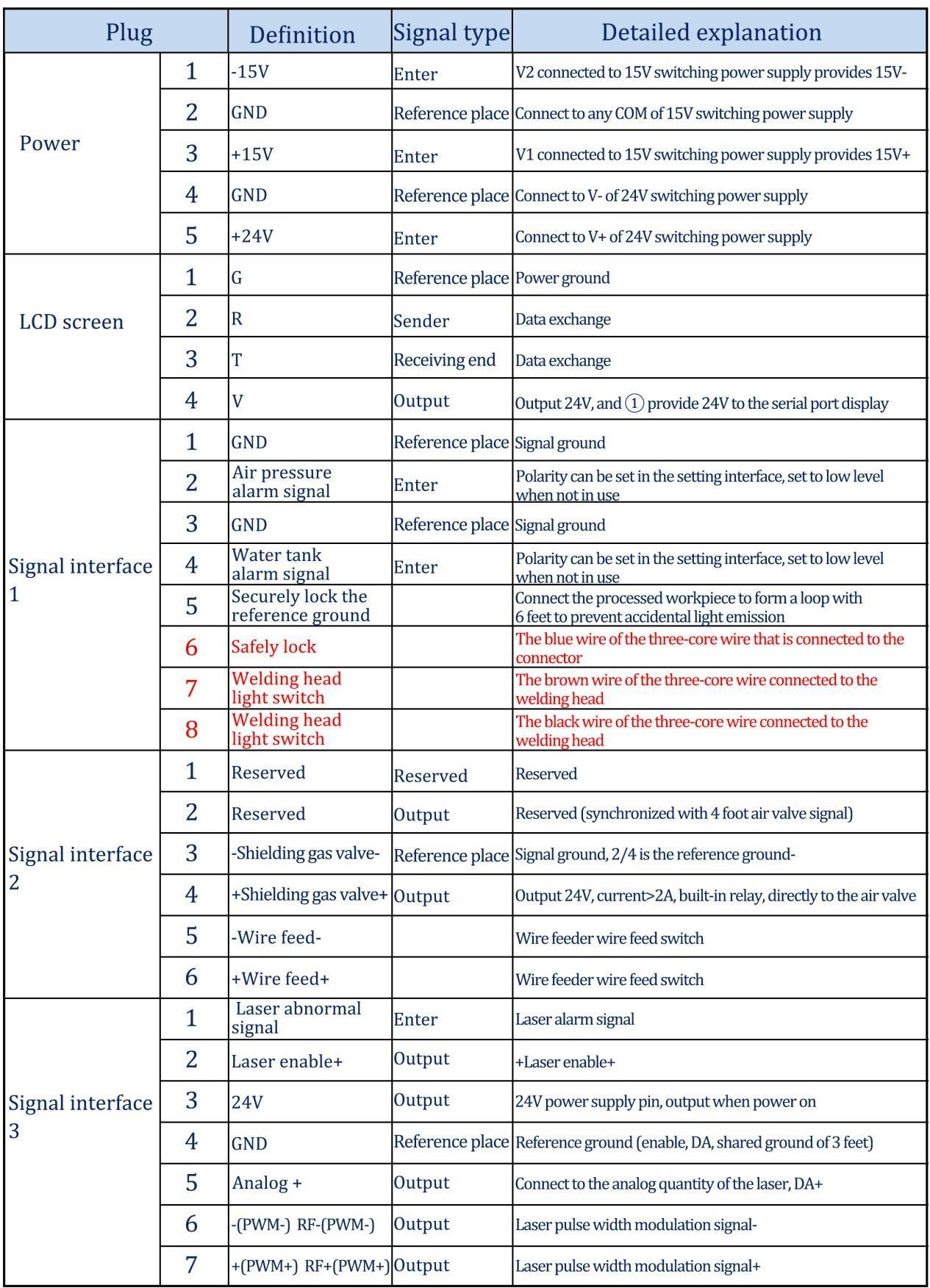
Controller power supply terminal
The power supply uses a 5P connector and is powered using the 24V switching power supply and 15V switching power supply provided.
Please note that the 15V switching power supply distinguishes between positive and negative, V1 is connected to 15V+, V2 is connected to 15V-, and any COM on the 15V switching power supply is connected to pin 2 GND!
Please note that the switching power supply must be grounded!
Controller LCD24/5000
The LCD cable is delivered with the device and can be connected directly. See the figure above for specific definitions
Controller signal interface 1
①/②Pin is the air pressure alarm signal input, if you need to enable (wiring required), please set the air pressure alarm level in the background as high, otherwise it is low
Pin ③/④ is the water tank alarm signal input. If you need to enable it (wiring required), set the air pressure alarm level to high in the background, otherwise it is low.
The number pin is the reference ground for the safety ground lock and is wired directly to the process workpiece.
The number pin is the safety ground lock for the weld head, connected to the blue wire of the three-core wire, when the weld head touches the workpiece, the safety lock is on at this time
Pin No. is the weld head’s on/off switch, connected to the brown wire of the three-core cord.
Pin No. is the light switch for the weld head, connected to the black wire of the three-core wire, when the trigger is pulled, the trigger button lights up.
Please note that the output signal of the subsequent ports will be sent only if there is no alarm and the signal of the safety lock and trigger button are on.
Controller signal interface 2
The signal interface 2 end uses a 6P interface, and the incoming line related to the air valve
① Reserved foot
② reserved pin (synchronized with 4-pin signal)
③/④ pin is the 24V output of air valve, connected to air valve
⑤/⑥ foot is the signal line of the wire feeder, which is the signal port of the wire feeder, and is not divided into positive and negative.
Controller wiring diagram
①/②Pin is the air pressure alarm signal input, if you need to enable (wiring required), please set the air pressure alarm level in the background as high, otherwise it is low
Pin ③/④ is the water tank alarm signal input. If you need to enable it (wiring required), set the air pressure alarm level to high in the background, otherwise it is low.
The number pin is the reference ground for the safety ground lock and is wired directly to the process workpiece.
The number pin is the safety ground lock for the weld head, connected to the blue wire of the three-core wire, when the weld head touches the workpiece, the safety lock is on at this time
Pin No. is the weld head’s on/off switch, connected to the brown wire of the three-core cord.
Pin No. is the light switch for the weld head, connected to the black wire of the three-core wire, when the trigger is pulled, the trigger button lights up.
Please note that the output signal of the subsequent ports will be sent only if there is no alarm and the signal of the safety lock and trigger button are on.
Controller signal interface 2
The signal interface 2 end uses a 6P interface, and the incoming line related to the air valve
① Reserved foot
② reserved pin (synchronized with 4-pin signal)
③/④ pin is the 24V output of air valve, connected to air valve
⑤/⑥ foot is the signal line of the wire feeder, which is the signal port of the wire feeder, and is not divided into positive and negative.
Controller signal interface 3
Pin is the laser alarm signal input +, if you want to enable, please set the air pressure alarm level to high level in the background
Pin is enable+, connect laser enable+.
Pin No. 3 is 24V output, output 24V+ directly after power on
Pin No. ④ is common ground (reference ground of pin 1/2/3/5)
Pin No. is analog + output, analog is given
Pin No. is PWM modulation signal
The digital pin is PWM+ modulating signal ⑦ The digital pin is PWM+ modulating signal
Controller wiring diagram
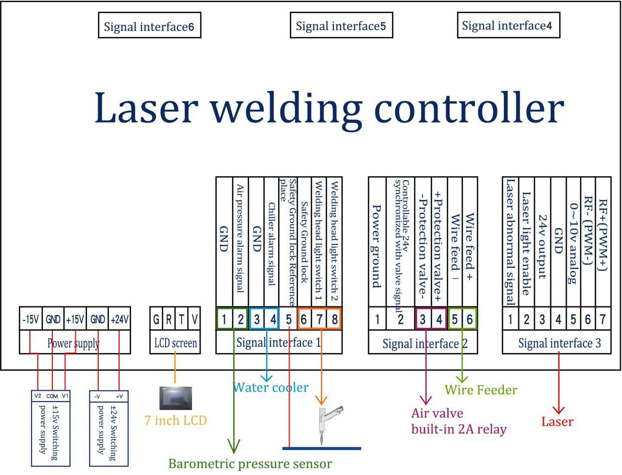
Note: The COM terminal of the ±15V switching power supply and the -V (0V) terminal of the +24V switching power supply must be connected to GND and fully connected to the workpiece at the same time. The case of the switching power supply must be connected to the ground, otherwise a safety lock ground alarm may occur and it will not light up.
Optical input interface
SUP welding heads are available for most industrial laser generators. Commonly used fiber optic interfaces are IPG, RICO, Troncin, FIBO, Tottenham, Jephte, Caplin, etc. The optics must be kept clean and cleared of all dust before use
When inserting the fiber, the cutting head must be rotated 90 degrees so that it is horizontal before using the fiber to prevent dust from falling into the interface.
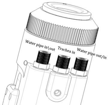
Shielding gas and water chiller interface
The water and gas pipe interface can be installed with a 6MM outer diameter and 4MM inner diameter hose. The gas line enters from the middle, and the water inlet and outlet pipes are on both sides (without considering the direction of water inlet and outlet), as shown below.
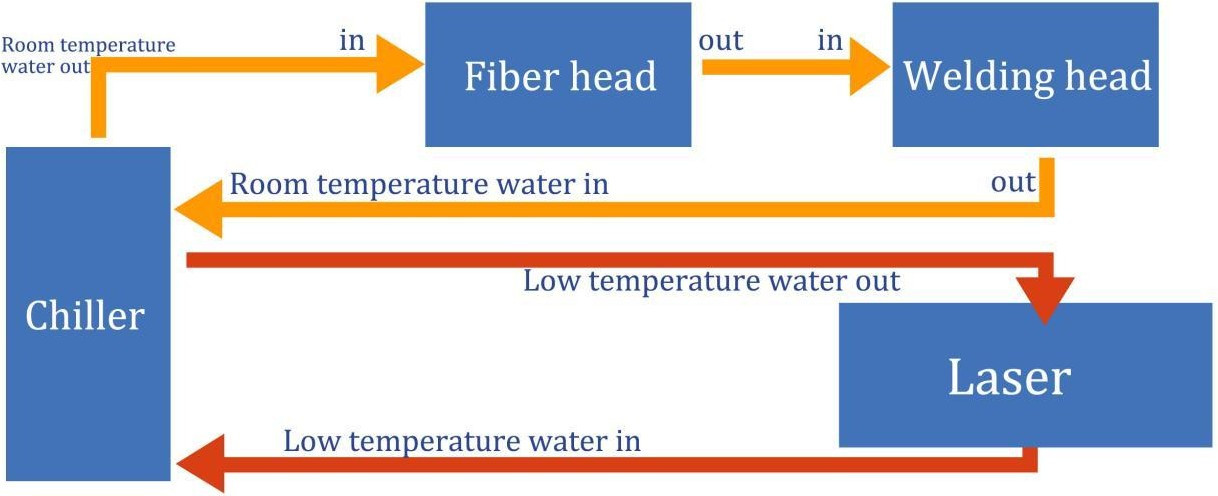
The cooling system is divided into the water circuit part of the welding head and the water circuit part of the optical fiber head, which are connected in series, as shown in the figure below:
Welding gun and control box connection interface
Connection interface of welding gun and control box
The welding gun is connected to the control box with three wires, including: two-core motor power wire, five-core motor signal wire, three-core safety ground lock and trigger button wire
The motor power/signal wires (two black wires) are directly connected to the motor part of the welding head and can be removed (two options: 1. Open the motor cover and side panel of the handheld torch 2. Open the control box Both are plugged in)
The safety lock and trigger button three-core wire used Removable airline plug: safety lock and button wire, of which 1 is blue, 2 is black, 3 is brown (connected to the signal interface 1 pin 6/7/8, see the wiring definition of the control box above).
Wire feeder installation
The two-core aviation plug at the end of the wire feeder is connected to pin 5/6 of signal interface 2. Please refer to the following for the specific installation method.
Click. Wire feeder installation instructions (Applets).
Control panel and operation guide (V3.3 version below).
Operation summary and operation guide
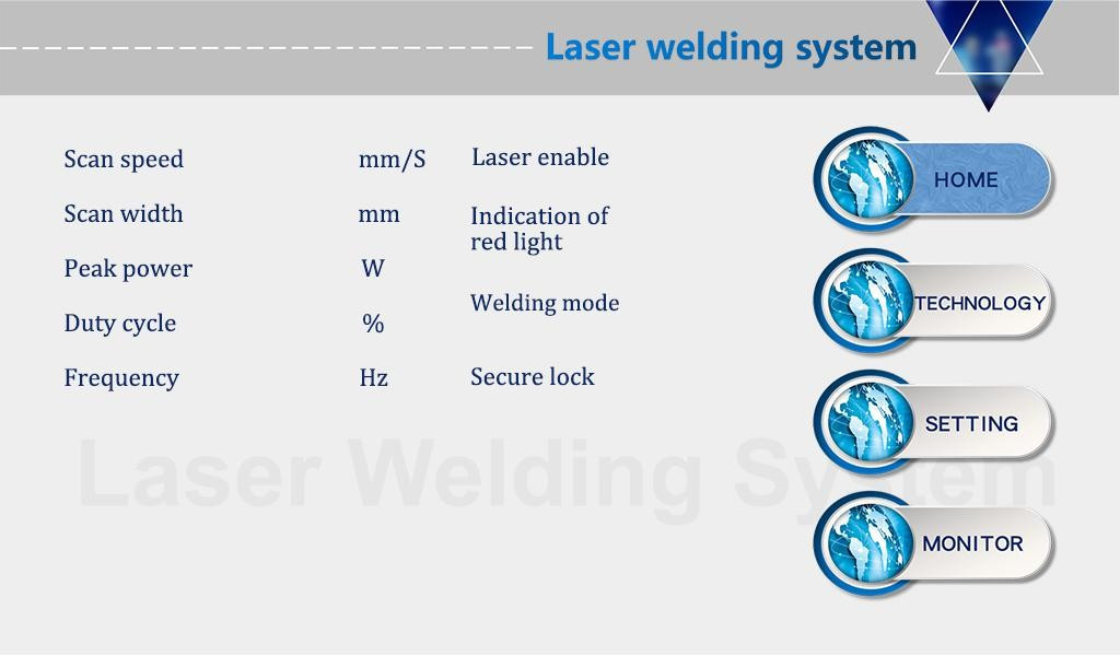
The operation panel of SUP series mainly consists of touch screen and control box.
Touch the main page, process, setting, monitoring and other operation screens.
Touch screen operation main screen
①In this screen, you can see the current process parameters and the instant alarm information.
②The laser is enabled and the indicator light is red when it is turned on.
③The safety lock is usually gray and turns green when the weld head touches the workpiece and the process can be performed.
④Welding mode is selected, and the default is continuous. When set to spot welding, it can intermittently glow for spot welding operation, which is easy to control the spot welding time due to human error. This function needs to be set as needed (V3.3 version for the above function)
Process operation main screen
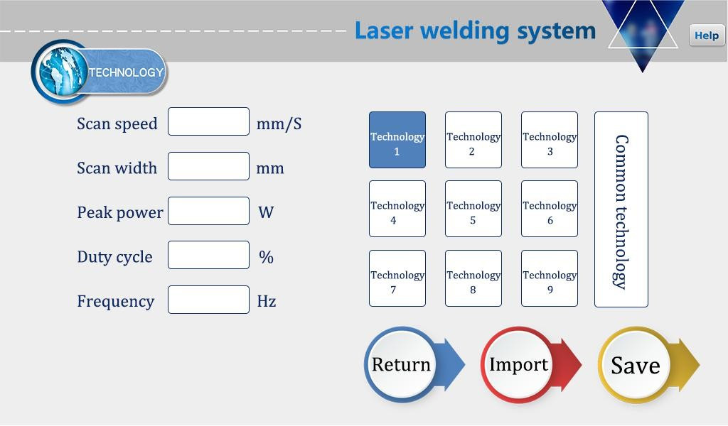
①The Process screen contains process parameters for debugging, which can be modified by clicking the box. After you finish modifying, click OK and then save it in Quick Process. To use, click Import (Modify – Save – Import).
②The scanning speed range is 2-6000mm/S and the scanning width range is 0^5mm. The scanning speed is limited by the scanning width. The limit relationship is. 10≤scanning speed/(scan width*2)≤1000 If the limit is exceeded, it will automatically become the limit value. When the scan width is set to 0, there will be no scanning (i.e. point source) (most common scan speed: 300mm/S, width 2.5mm).
The peak power must be less than or equal to the laser power on the parameter page (e.g., if the laser power is 1000W, the value is no higher than
1000).
④Load rate range is 0~100 (default is 100, usually no need to change).
The recommended pulse frequency range is 5-5000Hz (default is 2000, usually no need to change).
Click the “Help” button on the top right to get more explanations of the relevant parameters.
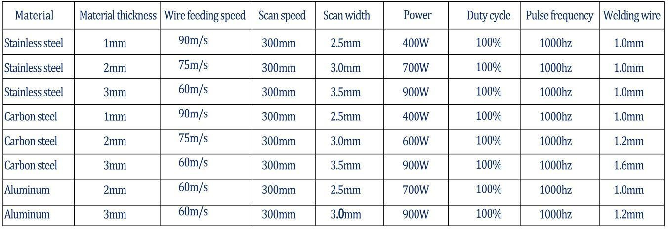
Process reference (subject to actual conditions, the following is for reference only)
Set operation main screen
Password 123456
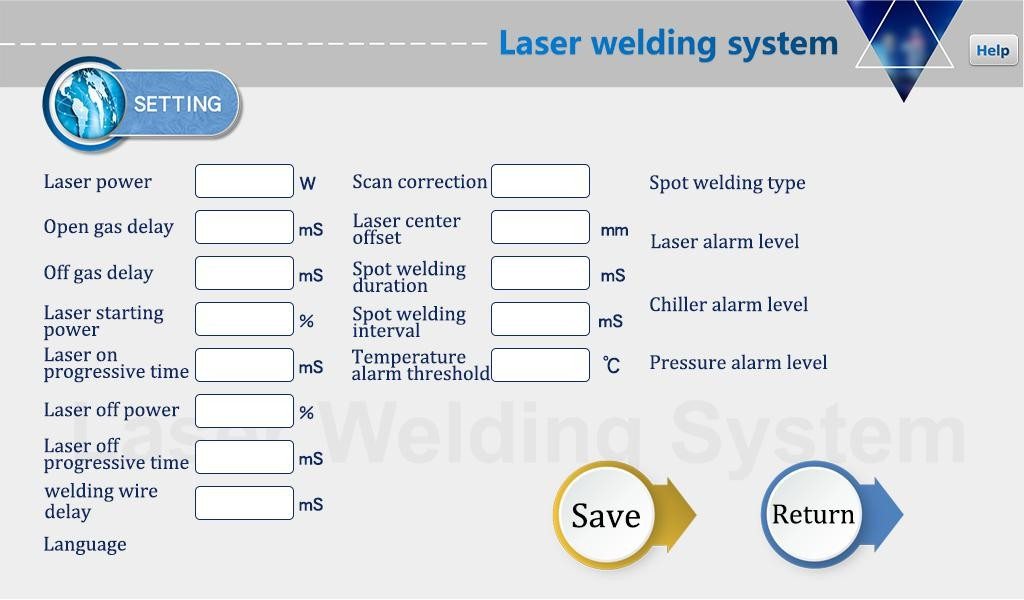
The laser power is the maximum power of the laser used.
②The switch air delay is 200ms by default, and the range is 200ms-3000ms.
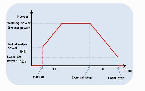
③The light on gradually increases from N1% to 100% of the process power; when the light is off, it gradually increases from 100% of the process power.
to N2; (as shown in the figure below).
④The line feed delay compensation is relative to the line feed advance time of the optical signal and can be used in conjunction with the undo function.
⑤ The maximum temperature alarm threshold is 70°C. When the value is set to 0, the temperature alarm will not be detected.
⑥Scanning correction coefficient range 0.01~4, coefficient target line width/measurement line width: generally 1.25.
⑦The laser center offset is -3~3mm, decreasing to the left and increasing to the right.
⑧ alarm level signal is the default, shield alarm can be directly changed to the corresponding level detection.
⑨ spot welding duration refers to the light-emitting time after pulling the trigger, that is, even if the button is released, it will still light up according to the time spent (V3.3 version for the above function)
Spot welding interval time is the stop light time between two spot welds after pulling the trigger button (V3.3 version of the above function)
⑧ Click the HELP button on the top right to get more explanation of the relevant parameters.
Monitoring main interface
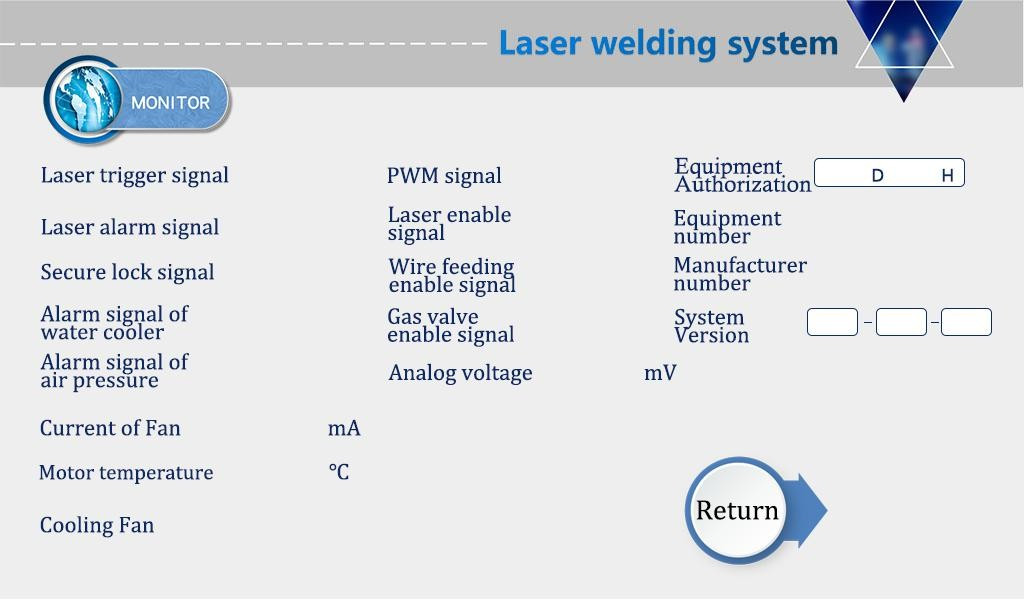
This interface shows the status of each detection signal and device information
Click on the device authorization to enter the authorized use time interface, after entering the password, the system can be authorized for the use time The authorization encryption and decryption methods are the same:
System decryption metho

This type of laser welding head is one of our hot sales products, it supports eight languages.