
Handheld laer welding gun SUP 21S


Handheld laer welding gun SUP 21S,
,
Safe. – Safe
Independent research and development of security detection system, set up a number of security alarms, security and stability
Time saving – efficient and convenient
Focus mirror, protection mirror drawer, convenient replacement
Lightness – Lightness reduces load
Smaller size, lighter weight, flexible operation, easy to use
Quality – beautiful welding – stable performance
High welding strength, small deformation, high melting depth
Performance – Multiple features
Support hand-held continuous welding, spot welding, cleaning, cutting, “hand” “since” – body, password authorization
Super welding head is a handheld welding cutting head launched in 2019. The product covers hand-held welding guns and self-developed control systems, and is equipped with multiple safety alarms and active safe power and light-off settings. This product can be adapted to various brands of fiber lasers; the optimized optical and water-cooled design allows the laser head to work stably for a long time under 3000W.
1)Ensure reliable grounding before power supply.
2)The laser output head is connected with the welding head. Please check the laser output head carefully when using it to prevent dust or other pollution. When cleaning the laser output head, please use special lens paper.
3)If the equipment is not used in accordance with the methods specified in this manual, it may be in abnormal working condition and cause damage.
4)When replacing the protective lens, please make sure to protect it.
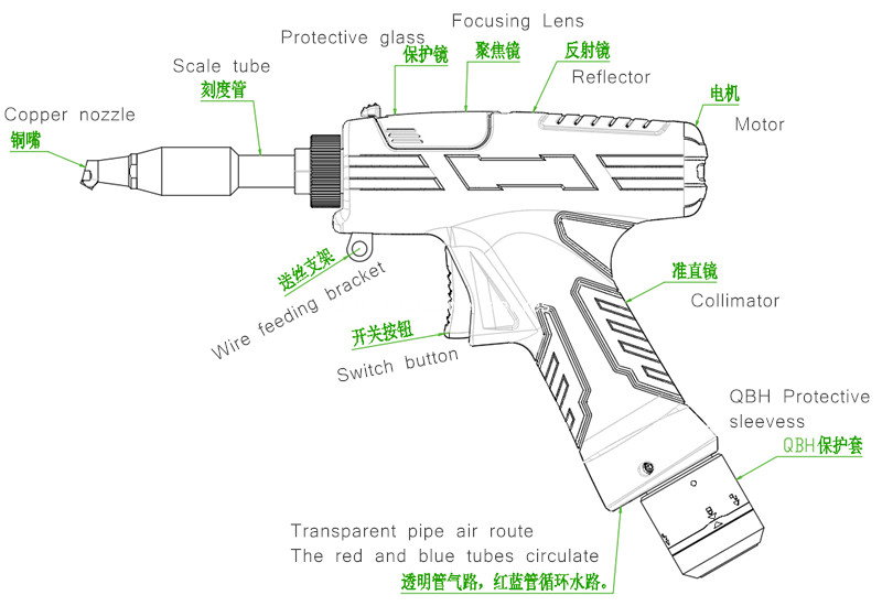
5)Please note: When using for the first time, when the red light cannot come out of the copper mouth, be sure not to emit light
Package Delivery Details
Hand-held welding head package delivery details
★ First layer
SUP20S welding head 1pc
System 1 set
System cable standard 10m
★ Second layer
Copper nozzle 7pcs Cutting nozzle 1pc
Scale tube 1pc
Protective lens 10pcs
Ground clamp 1pc
Screen connection cable 1m
Display screen buckle 1set
Third layer
Display screen 1pcs
ower switch 2pcs
Controller wiring definition
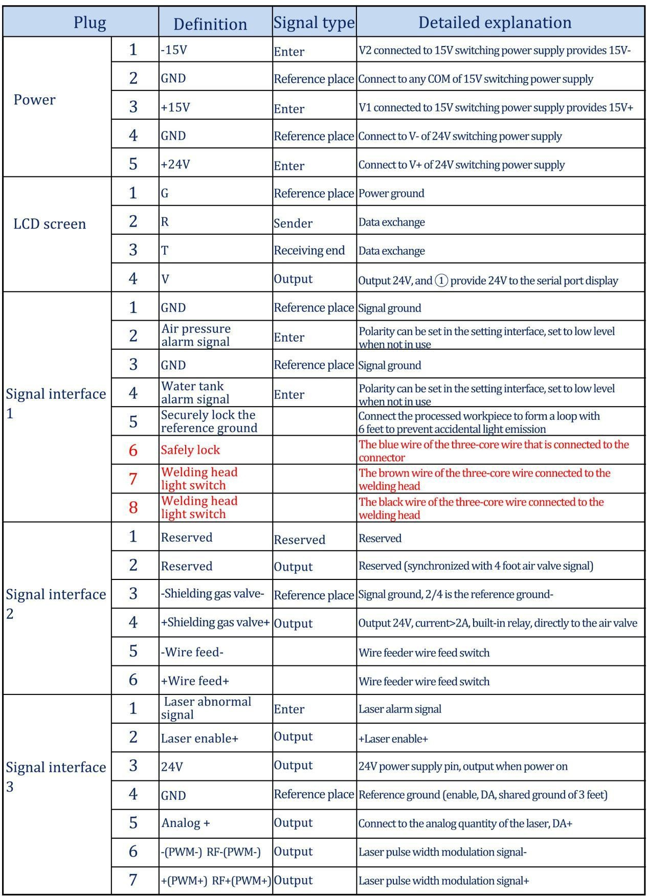
Controller power supply terminal
The power supply uses the 5P interface, and the supplied 24V switching power supply and 15V switching power supply are used for power supply
Please note that the 15V switching power supply distinguishes the positive and negative poles, V1 is connected to 15V+, V2 is connected to 15V-, and any COM on the 15V switching power supply is connected to pin 2 GND!
Please note that the switching power supply must be grounded!
Controller LCD24/5000
The LCD cable is delivered with the device and can be connected directly. See the figure above for specific definitions
Controller LCD24/5000
The LCD cable is delivered with the device and can be connected directly. See the figure above for specific definitions
Controller signal interface 1
①/②Pin is the air pressure alarm signal input, if you need to enable (wiring required), please set the air pressure alarm level in the background as high, otherwise it is low
The ③/④ pin is the water tank alarm signal input. If you need to enable it (wiring is required), please set the air pressure alarm level in the background as high, otherwise it is low
⑤The number pin is the reference ground for the safety ground lock, and it is directly connected to the processing workpiece with a wire
⑥ No. pin is the safety ground lock of the welding head, connected to the blue wire of the three-core wire, when the welding head touches the workpiece, the safety lock is on at this time
⑦The number pin is the switch of the welding head, connected to the brown wire of the three-core wire
⑧Pin No. is the light switch of the welding head, connected to the black wire of the three-core wire, when the trigger is pulled, the trigger button is on
Please note that only when there is no alarm, and the signal of the safe lock and trigger button is on, the output signal of the subsequent port will be sent out.
Controller signal interface 2
The 2 end of the signal interface uses a 6P interface, and the air valve is related to the wire feeding
①Reserved feet
②Reserved feet (synchronized with 4-pin signal)
③/④The foot is the valve 24V output, connect to the valve
⑤/⑥The pin is the signal wire of the wire feeder, the signal port of the wire feeder, regardless of positive or negative
Controller signal interface 3
①Pin is the laser alarm signal input +, if you need to enable it, please set the air pressure alarm level to high in the background
②Pin is enable+, connect to laser enable+
③The pin is 24V output, directly output 24V+ after power on
④Pet No. is a common ground (reference ground for feet 1/2/3/5)
⑤The number pin is analog quantity + output, the analog quantity is given
⑥Pin is PWM-modulated signal
⑦The number pin is PWM+ modulation signal
Controller wiring diagram
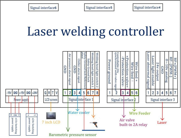
Note: The COM terminal of ±15V switching power supply and the -V (0V) terminal of +24V switching power supply must be connected to GND and fully connected to the workpiece at the same time. The shell of the switching power supply must be connected to the ground, otherwise, a safety ground lock alarm may occur, and no light will be emitted.
Optical input interface
SUP welding head is suitable for most industrial laser generators. Commonly used optical fiber connectors include IPG, Ruike, Chuangxin, Fibo, Tottenham, Jept, Kaplin, etc. The optics must be kept clean and all dust must be removed before use
When the fiber is inserted, the cutting head must be rotated 90 degrees to be horizontal, and then the fiber is used to prevent dust from falling into the interface.
installation method(Applets )
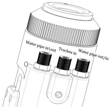
Shielding gas and water chiller interface
The water pipe and air pipe interface can be installed with hoses with an outer diameter of 6MM and an inner diameter of 4MM. The air path enters in the middle, and the two sides are Water inlet and outlet pipelines (regardless of the direction of inlet and outlet) , As shown below:
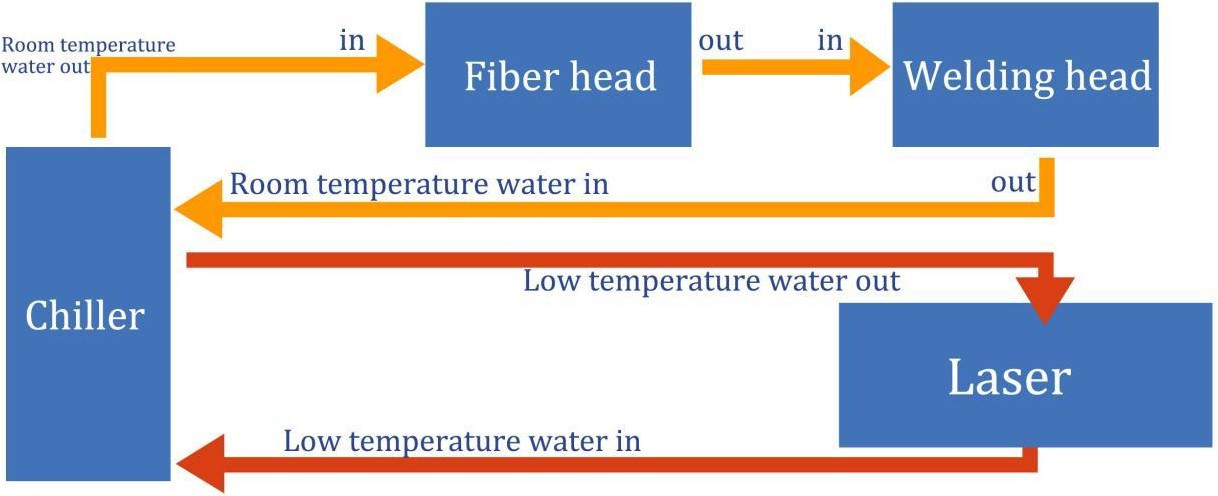
The cooling system is divided into the water circuit part of the welding head and the water circuit part of the optical fiber head, which are connected in series, as shown in the figure below:
Welding gun and control box connection interface
The welding gun and the control box use three wires to connect, including: two-core motor power line, five-core motor signal line, three-core safety ground lock and trigger button line
The motor power/signal wires (two black wires) are directly connected to the motor part of the welding head and can be disassembled (two options are available:1. Open the motor cover and side plate of the handheld welding gun 2. Open the control box All are plugs)
Safely lock and trigger button three-core wire used Removable aviation plug:Safely lock and button wires, of which 1 is blue, 2 is black, and 3 is brown (connected to pin 6/7/8 of signal interface 1, see the wiring definition of the control box above for details)
Wire feeder installation
The two-core aerial plug at the tail of the wire feeder is connected to pin 5/6 of signal interface 2. Refer to the following for the specific installation method
Click: Wire Feeder Installation Instructions(Applets)
Control panel and operation guide (the following is V3.3 version)
Operation summary and operation guide
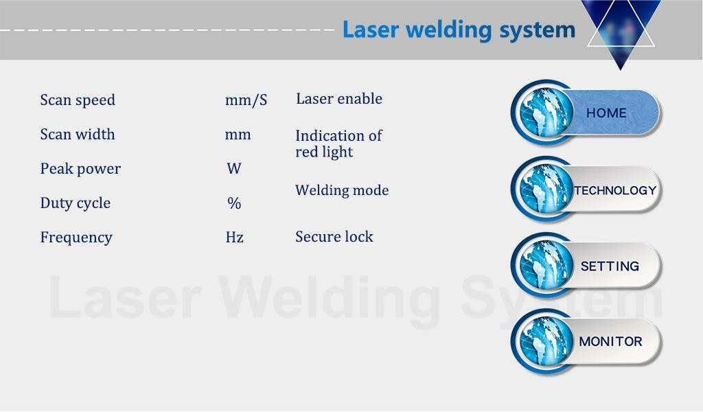
The operation panel of SUP series is mainly composed of touch screen and control box.
Touch the main page, process, setting, and monitoring of the operation interface.
Touch screen operation main screen
①In this interface, you can see the current process parameters and instant alarm information.
②The laser is enabled and the indicator red light is ON when it is turned on.
③The safety lock is usually gray, and when the welding head touches the workpiece, it becomes green and can be processed.
④ Welding mode selection, the default is continuous. When it is set to spot welding, it can emit light intermittently for spot welding operation, which is convenient for controlling the spot welding time due to human error. This function needs to be set as needed (V3.3 version is the above function)
Process operation main screen
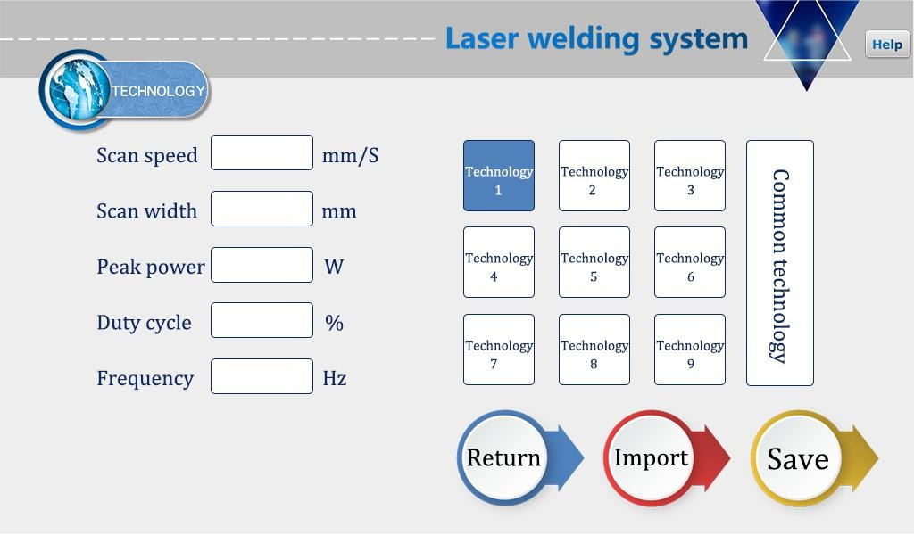
①The process interface contains the process parameters for debugging, which can be modified by clicking the box. After the modification is completed, click OK, and then save it in the shortcut process. When using it, click Import (Modify-Save-Import).
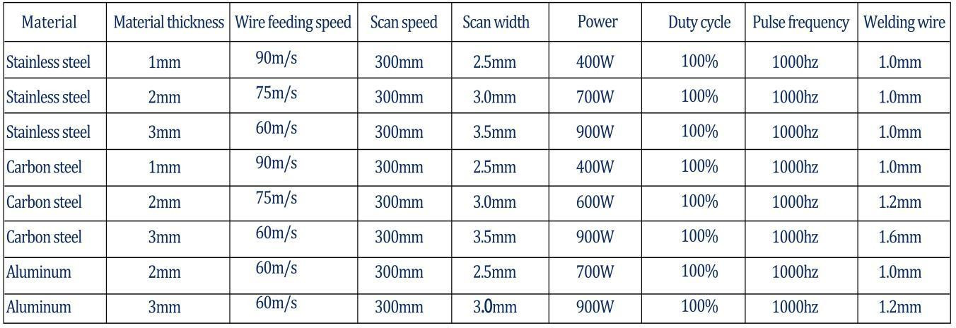
②The scanning speed range is 2-6000mm/S, and the scanning width range is 0^5mm. The scanning speed is limited by the scanning width. The limitation relationship is: 10≤scanning speed/(scanning width*2) ≤1000 If it exceeds the limit, it will automatically become the limit value. When the scan width is set to 0, it will not scan (ie point light source) (the most commonly used scan speed: 300mm/S, width 2.5mm).
③The peak power must be less than or equal to the laser power on the parameter page (for example, the laser power is 1000W, then the value is not higher than
1000).
④Duty ratio range 0~100 (default 100, usually do not need to change).
⑤The recommended pulse frequency range is 5-5000Hz (the default is 2000, usually it does not need to be changed).
⑥Click the HELP button on the upper right to get more related parameter explanations.
Process reference (subject to actual conditions, the following is for reference only)
Set operation main screen
Password 123456
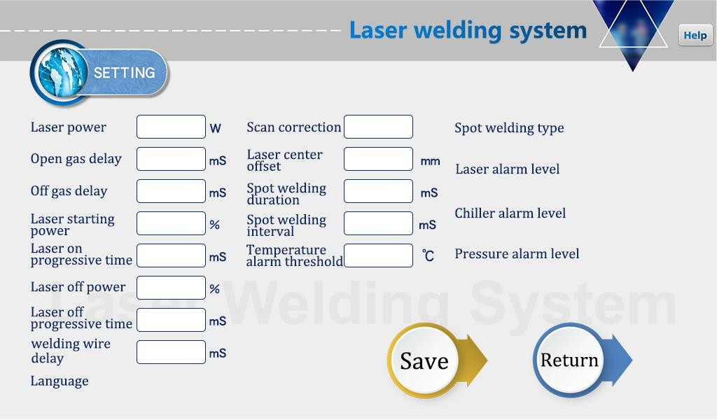
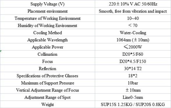
①The laser power is the maximum power of the laser used.
②The switch air delay defaults to 200ms, and the range is 200ms-3000ms.
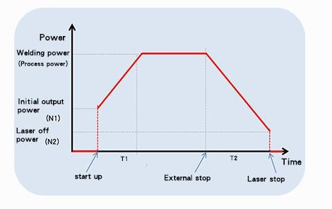
③When the light is turned on, it will gradually increase from N1% of the process power to 100%; when the light is turned off, it will gradually increase from 100% of the process power.
To N2; (as shown in the figure below).
④Wire feeding delay compensation is the wire feeding advance time relative to the light signal, which can be used in conjunction with the withdrawal function.
⑤The maximum temperature alarm threshold is 70℃. When the value is set to 0, the temperature alarm will not be detected.
⑥Scan correction coefficient range 0.01~4, coefficient target line width/measurement line width: generally 1.25.
⑦Laser center offset -3~3mm, reduce it and move it to the left, increase it and move it to the right.
⑧The alarm level signal is the default, and the shielded alarm can be directly changed to the corresponding level detection.
⑨Spot welding duration is the light emitting time after pulling the trigger, that is, even if the button is released, the light will still be emitted according to the time spent (V3.3 version is the above function)
⑩Spot welding interval time is the stop light time between two spot welding after pulling the trigger button (V3.3 version and above function)
⑧Click the HELP button on the upper right to get more related parameter explanation.
Monitoring main interface
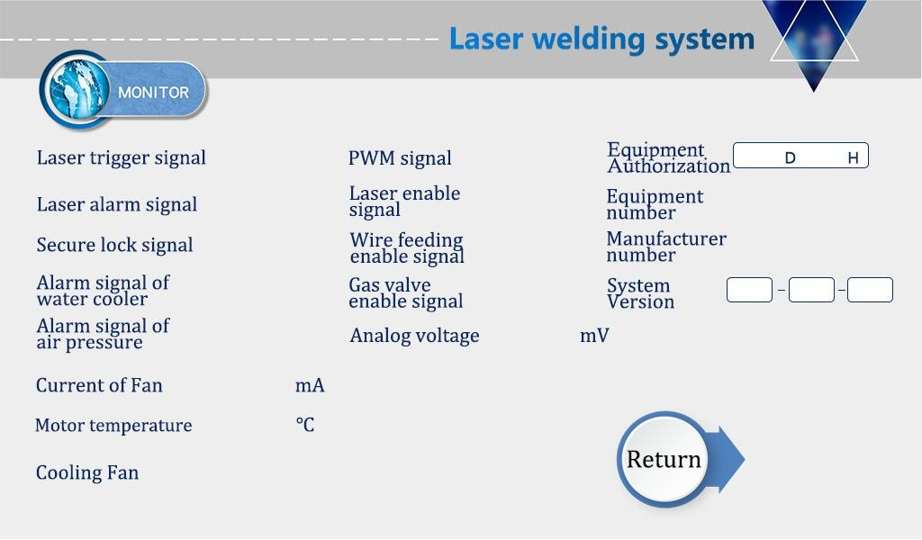
This interface shows the status of each detection signal and device information
Click on the device authorization to enter the authorized use time interface, after entering the password, the system can be authorized for the use time
The authorization encryption and decryption methods are the same:
System decryption metho (Apple)SUP21S is the updated one of SUP20S, it is lighter and more powerful .